
When you have coordination challenges, turn to Runsheng Transformer for help
It's all about making things easy, building partnerships, and providing a point of contact.

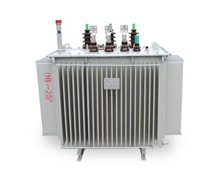
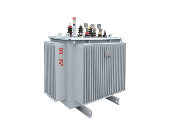
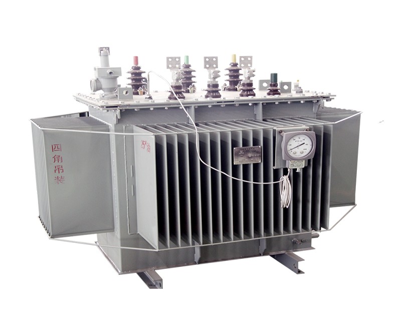
Item:Oil Transformer
①Vacuum filter filling of transformer oil
②Stable electrical performance
③High dynamic stability
④Good thermal stability
⑤High overload capacity
⑥Long service life


Oil transformers have stable electrical performance, strong overload capacity and no need to change oil during normal operation, which greatly reduces the maintenance cost of the transformer and extends the service life of the transformer.
Oil transformer is a structural type of transformer, i.e., the transformer's coils are immersed in oil. Oil-immersed transformers are generally installed in separate transformer rooms or outdoors due to the need for fire protection, and are characterized by large size, low cost, simple maintenance, good heat dissipation, high overload capacity, and wide adaptation to the environment.
Oil transformers are important components of substations and are generally installed in a separate transformer room. Relying on oil as the cooling medium, such as oil-immersed self-cooling, oil-immersed air-cooling, oil-immersed water-cooling and forced oil circulation, etc..
Generally, the main transformer of booster station is oil-immersed, the ratio is 20KV/500KV, 20KV/220KV, and the plant transformer used in general power plant to drive with its own load (such as coal mill, induced draft fan, fan, circulating water pump, etc.) is also oil-immersed transformer, its ratio is 20KV/6KV.


S:Three phase
▢:"F" means air-cooled self-cooling without code
▢:"Z" means on-load voltage regulation without action,with magnetic load regulation and voltage regulation without code
▢:Performance level code
▢:Rated Capacity(kVA)
▢:Voltage class(kV)
● Installation altitude: no more than 1000m above sea level
● Ambient temperature: -40℃~+40℃
■ 800KVA-31500KVA Three-phase double-winding non-excitation voltage regulating power transformer: | |||||||||
Model | Rated capacity (KVA) | Link group label | Voltage combination (KV) | No-load loss (W) | Load loss (W) | No-load current(%) | Short circuit impedance (%) | Tap range | Low pressure |
high pressure | |||||||||
S11-630 | 630 | Yd11 | 35 | ±5% | 3.15 6.3 10.5 | 830 | 7870 | 1.10 | 6.5 |
S11-800 | 800 | 980 | 9410 | 1.00 | |||||
S11-1000 | 1000 | 1150 | 11540 | 1.00 | |||||
S11-1250 | 1250 | 1410 | 13940 | 0.90 | |||||
S11-1600 | 1600 | 1700 | 16670 | 0.80 | |||||
S11-2000 | 2000 | 2180 | 18380 | 0.70 | |||||
S11-2500 | 2500 | 2560 | 19670 | 0.60 | |||||
S11-3150 | 3150 | 35 ~ 38.5 | ±5% | 3.15 6.3 10.5 | 3040 | 23090 | 0.56 | 7.0 | |
S11-4000 | 4000 | 3620 | 27360 | 0.56 | |||||
S11-5000 | 5000 | 4320 | 31380 | 0.48 | |||||
S11-6300 | 6300 | 5250 | 35060 | 0.48 | 7.5 | ||||
S11-8000 | 8000 | YNd11 | 35 ~ 38.5 | ± 5% | 3.15 3.3 6.3 6.6 10.5 11 | 7200 | 38500 | 0.42 | |
S11-10000 | 10000 | 8700 | 45300 | 0.42 | |||||
S11-12500 | 12500 | 10080 | 53900 | 0.40 | 8.0 | ||||
S11-16000 | 16000 | 12160 | 65800 | 0.40 | |||||
S11-20000 | 20000 | 14400 | 79500 | 0.40 | |||||
S11-25000 | 25000 | 17020 | 94100 | 0.32 | |||||
S11-31500 | 31500 | 20220 | 112900 | 0.32 | |||||
| Note 1: Transformers with a rated capacity of 6300KVA and below can provide products with a high-voltage tap range of +2x2.5%. | |||||||||
Note 2: For transformers with lower voltages of 10.5KV and 11KV, products with connection group designation Dyn11 can be provided. | |||||||||
Note 3: For transformers with rated capacity of 3150KVA and above, the -5% tap position is the maximum current tap. | |||||||||
■ 2000KVA-20000KVA Three-phase double-winding on-load voltage regulating power transformer: | |||||||||
Model | Rated capacity (KVA) | Link group label | Voltage combination (KV) | No-load loss (W) | Load loss (W) | No-load current(%) | Short circuit impedance (%) | ||
high pressure | Tap range | Low pressure | |||||||
SZ11-2000 | 2000 | Yd11 | 35 | ±3x2 5% | 6.3 | 2300 | 19240 | 0.80 | 7 |
SZ11-2500 | 2500 | 10.5 | 2720 | 20640 | 0.80 | ||||
SZ11-3150 | 3150 | ±3x2 5% | 3230 | 24710 | 0.72 | ||||
SZ11-4000 | 4000 | 35 ~ 38.5 | 6.3 | 3870 | 29160 | 0.72 | 7.0 | ||
SZ11-5000 | 5000 | 10.5 | 4640 | 34200 | 0.68 | ||||
SZ11-6300 | 6300 | 5630 | 36800 | 0.68 | |||||
SZ11-8000 | 8000 | YNd11 | ±3x2.5% | 6.3 | 7870 | 40600 | 0.60 | 7.5 | |
SZ11-10000 | 10000 | 6.6 | 9280 | 48100 | 0.60 | ||||
SZ11-12500 | 12500 | 35 ~ 38.5 | 10.5 | 10940 | 56900 | 0.56 | |||
SZ11-16000 | 16000 | 11 | 13170 | 70300 | 0.54 | 8.0 | |||
SZ11-20000 | 20000 | 15570 | 82800 | 0.54 | |||||
| Note 1: For transformers with low voltage voltages of 10.5KV and 11KV, products with connection group designation Dyn11 can be provided. | |||||||||
Note 2: Maximum current tap is -7.5% tap position. | |||||||||


Runsheng Transformer Co., Ltd. is a professional manufacturer of power transformers, specializing in oil-immersed transformers (S20, S11, S13), SH15 amorphous alloy transformers, S13 series 10KV 3D magnetic path wound-core transformers, D10 single-phase wound-core transformers, as well as mining transformers, rectifier transformers, surge arrestor transformers, load-tap-changing transformers, and custom-engineered special transformers.
WhatsApp & Wechat

No. 6, Intersection of Mount Huangshan Road and Changjiang Road, Liaocheng High tech Industrial Development Zone, Shandong, China


